


{{ name }}
Article no. {{ combinedCodeWithHighlight }}
Article code:
EAN / GTIN:
Manufacturer number:

 Download now (PDF)
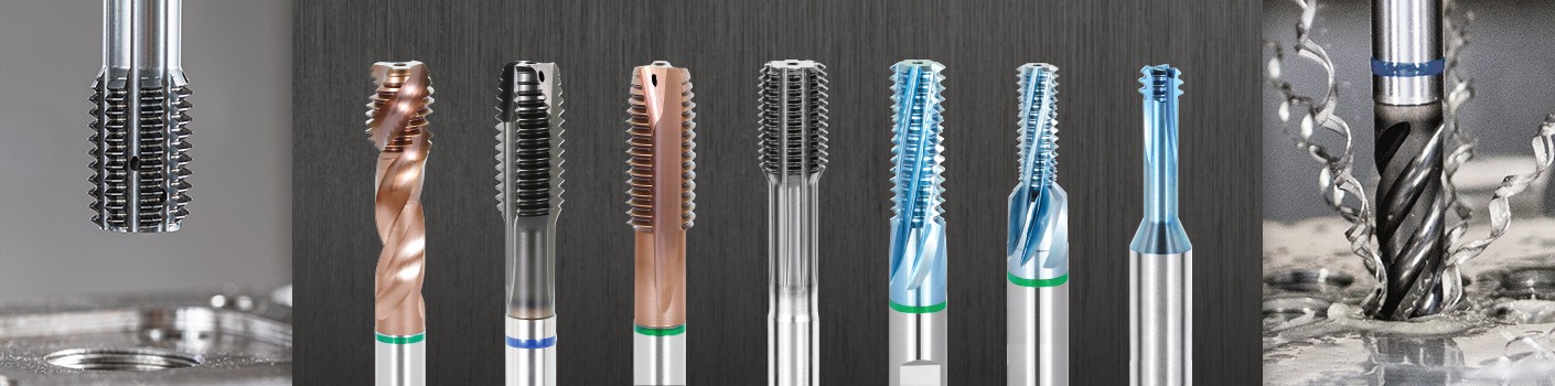
In production technology, the generation of internal threads ranks amongst the most demanding of all machining tasks.
Thread generation often takes place at the end of a production process, and is thus critical for the quality of the workpiece. Defective threads generally mean high additional costs. Process reliability is absolutely the top priority, but short cycle times and cost-effective production processes must also be achieved.
1. The Manufacturing Process: Thread tapping
2. Herstellungsverfahren: Gewindeformen
3. Herstellungsverfahren: Gewindefräsen
4. Herstellungsverfahren: Bohrzirkulargewindefräsen

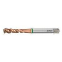
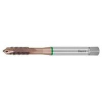
Thread tapping is the most widely known process for generating internal threads.
High productivity, relatively low costs and universal operational capabilities (on conventional machine tools, transfer systems, machining centres) are the main considerations. Taps are available in HSS / HSS-E / HSS-E-PM / solid carbide to satisfy the particular requirements of the user.
Special considerations when tapping threads
When tapping threads there is a form fit between tool and workpiece. The thread size, thread pitch and tolerance are precisely defined by the tap itself. However this causes specific machining problems not found with drilling or milling:
When selecting a tap, the longest possible lead chamfer form should be selected. A longer lead chamfer places less stress on the tool, thus reducing the load on the cutting edges. This aspect is increasingly significant as the tensile strength of the material increases.
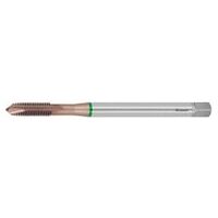
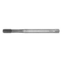
With these (straight-fluted) taps with a spiral point, the chips are evacuated downwards in the feed direction and fall out downwards when the tool is withdrawn. Therefore these tools are unsuitable for use in blind holes. When the direction of rotation is inverted (reversed), the compressed chip is not sheared off and becomes jammed.
If these taps are used in blind holes, damage to the thread or breakage of the tool is inevitable. Straight-fluted taps without a spiral point are used for machining brittle materials. Due to the tendency of brittle materials to form discontinuous chips, tools of this design can be used both for tapping through holes and also for tapping blind holes.

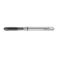
6 - 8 turns lead chamfer, for short through holes.

4 - 5 turns with spiral point, general purpose for through holes

4 - 5 turns lead chamfer, for through holes or blind holes
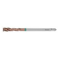
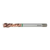
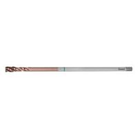
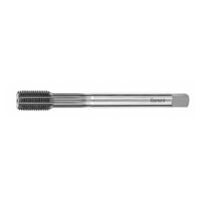
In general the generation of a thread in a blind hole places greater demands on the tool. The chips must be evacuated upwards through the chip flutes. When reversing and shearing off the chips at the root the tap is subjected to high torsional forces.

4 - 5 turns lead chamfer, for blind holes with long thread runout.

2 - 3 turns lead chamfer, for universal range of use.

1.5 - 2 turns lead chamfer, short thread runout for the greatest possible depths of thread.
Taps are divided into groups by the Hoffmann Group for simple and correct selection of the product.

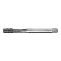
The thread forming process generates the threads by cold deformation; chip formation and chip evacuation are no longer required. Thanks to this advantage, the fluteless tap can be used with good process reliability for generating threads in blind holes and through holes, even with critical L×D ratios and thread depths greater than 4×D.
Load phases in the thread forming process
In the thread forming process, the torque load on the tool is up to 30% greater than for the thread tapping process. Since a fluteless tap does not require chip grooves for evacuation of chips, the core diameter of the tool can be designed for greater stability. This means that a fluteless tap can achieve good process reliability even when used for the most demanding processes.
The following factors have the greatest influence on the torque development:
In order to keep the torque forces as low as possible, the optimum tapping diameter and a high-quality lubricating medium should be chosen
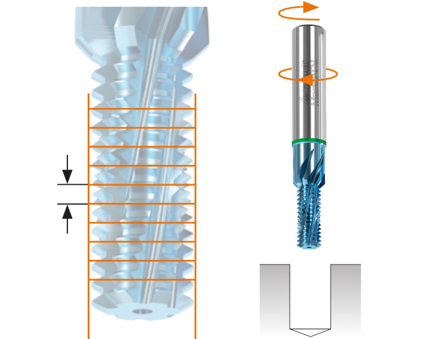
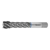
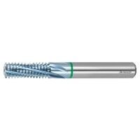
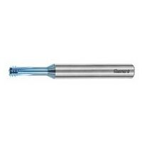
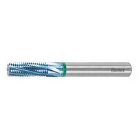
3D CNC control is a pre-requirement for the performance of thread milling. After adjustment to the working depth the tool describes a spiral and radial movement into the workpiece so as to reduce the loading. By rotation of the thread mill and simultaneous movement of the three main axes of the machining centre, the thread is now produced in a 360° movement.
Thread mills offer many potential applications:
Optimisation for use of thread mills
Normally with a thread mill the complete thread is generated in a single 360° movement. For special requirements it may be preferable to employ a divided cut. A change to the direction of rotation may also help optimise the results.
Workpiece programming:
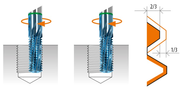
The thread is first cut about 2/3 of the depth and then is cut to the finished profile in a second pass.

Here part of the thread is produced first and then the full depth of the thread is machined.
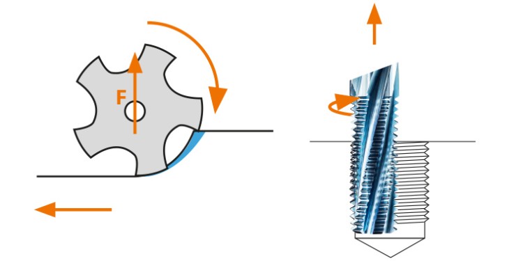
The radial force F acts in the direction of the centre. The chip thickness is small at the point of cutter exit

The radial force acts in the direction of the workpiece. The chip thickness is greater at the point of cutter exit
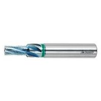
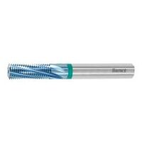
End cutting thread mill
In the end cutting thread milling process, certain deviations in the machining strategy must be observed, which differ from standard thread milling.
Cutting force distribution
With an end cutting thread mill the thread is completed to the full thread depth in a single machining cycle. No cutting force distribution is necessary, since the radial forces that occur remain constant even at different thread depths.
Tool set-up
Using the specified programming radius (RPRG value), which is laser etched on the shank, the user can generate threads true to the thread gauge, right from the first thread.
The strategy
The end cutting thread mill is designed for left-handed cutting. Thus the machining is carried out as climb milling for right-hand threads, and as opposed milling for left-hand threads. Cooling with compressed air permits very high production quantities per tool in hardened materials up to 63 HRC. The thread protection countersink can be created either before the actual thread milling process or after it.
Thread milling process
The end face geometry creates the core diameter of the thread. The end face is designed so that when the middle of the thread tolerance band is achieved, the core hole ⌀ lies within the core hole tolerance. Thus the gauge size of the core hole and also of the thread is achieved. The first cutting edge of the end cutting thread mill serves as the taper lead-in for the thread profile. In the thread milling process, it performs the main machining work of generating the finished thread profile. The second cutting edge performs the finishing work. The machining work of the third cutting edge is very little, it serves to clean the thread rather than performing a pass without cutting.

A 3D CNC control system is also precondition for the use of an end cutting thread mill, just as it is for a thread mill. Unlike thread milling, the end cutting thread mill plunges into the material with a helical movement without drilling a core hole. Drilling, thread milling and chamfering can be performed in just a single operation.
End cutting thread milling as problem solver for a very wide range of requirements:
An end cutting thread mill ensures process reliability, especially for final machining tasks on complex components. It is ideally suited to generating a thread on surfaces that are skew or are not flat.
Thread entry and exit surfaces that are skew will not cause the end cutting thread mill to run off line. It is also suitable for unstable clamping conditions. This tool offers excellent process reliability even for difficult to machine materials up to 63 HRC.